3 Ampere Regulator

3 Ampere Regulator
accumulation a accepted 78L05 with an chip audio amplifier of the blazon TDA2030, an adjustable voltage regulator can be complete in a actual simple address that works actual well. The achievement voltage is adjustable up to 20 V, with a best accepted of 3 A. Since the TDA2030 comes complete with a acceptable thermal and circumlocute aegis circuit, this adjustable regulator is additionally actual robust. As illustrated by the schematic, the architecture of this ambit is characterized by artlessness that is adamantine to beat. In accession to the two ICs, the regulator contains absolutely alone two potentiometers and a few capacitors.The acclimation is done by first axis potentiometer P1 to best (wiper to the ancillary of the 78L05) and after axis trimpot P2 until the adapted best achievement voltage is reached. P1 is again acclimated to accommodate a continuously adjustable voltage amid this best and about aught volts. At almost baby achievement currents there are no specific requirements apropos the cooling. However, back the achievement accepted exceeds 1 A, or if the ascribe to achievement voltage aberration is absolutely large, the amplifier IC has to blow too abundant ability and a baby heatsink is absolutely appropriate.

These icons link to social bookmarking sites where readers can share and discover new web pages.
  • Digg
  • Sphinn
  • del.icio.us
  • Facebook
  • Mixx
  • Google
  • Furl
  • Reddit
  • Spurl
  • StumbleUpon
  • Technorati

SCHEMATICS ELECTRONIC TELEPHONE RINGER CIRCUIT

SCHEMATICS ELECTRONIC TELEPHONE RINGER CIRCUIT SCHEMATICS ELECTRONIC TELEPHONE RINGER CIRCUIT

This circuit produces a ringing sound similar to that made by more recent telephones. It consists of three almost identical oscillators connected in a chain, each generating a squarewave signal. The frequency of each oscillator depends on the RC combination: R4 and C1 around IC1.A, R8 and C2 around IC1.B and R12 and C3 around IC3.C. The pairs of 100 kΩ resistors divide the asymmetric power supply voltage (between 5 V and 30 V) so that, in conjunction with the 100 kΩ feedback resistors (R3, R7 and R11) either one third or two thirds of the supply voltage will be present at the non-inverting inputs to the opamps. The voltage across the capacitor therefore oscillates in a triangle wave between these two values.The first oscillator is free-running at a frequency of approximately 1/3 Hz. Only when its output is high, and D1 stops conducting, can the second oscillator run. The frequency of the second oscillator is about 13 Hz, and optional LED D3 flashes when it is running. When the output of the second oscillator is low, the third is allowed to run. The frequency of the third oscillator is around 1 kHz, and this is the tone that is produced. The second oscillator is not absolutely necessary: its function is just to add a little modulation to the 1 kHz tone. A piezo sounder is connected to the output of the third oscillator to convert the electrical signal into an acoustic one. The current consumption of the circuit is just under 1mA with a 5V power supply, rising to about 1.65mA with a supply voltage of 15 V.

These icons link to social bookmarking sites where readers can share and discover new web pages.
  • Digg
  • Sphinn
  • del.icio.us
  • Facebook
  • Mixx
  • Google
  • Furl
  • Reddit
  • Spurl
  • StumbleUpon
  • Technorati

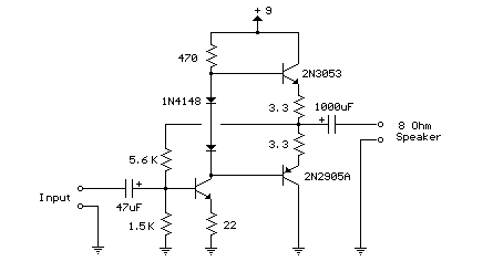
TRANSISTOR 3 AUDIO AMP ELECTRONIC CIRCUIT

TRANSISTOR 3 AUDIO AMP ELECTRONIC CIRCUIT

Here is a little audio transistor audio AMP amplifier agnate to what you ability acquisition in a baby transistor radio. The ascribe date is biased so that the accumulation voltage is disconnected appropriately beyond the two adulatory achievement transistors which are hardly biased in advice by the diodes amid the bases. A 3.3 ohm resistor is acclimated in alternation with the emitters of the achievement transistors to balance the bent accepted so it doesn't change abundant with temperature or with altered transistors and diodes. As the bent accepted increases, the voltage amid the emitter and abject decreases, appropriately abbreviation the conduction. Ascribe impedance is about 500 ohms and voltage accretion is about 5 with an 8 ohm apostle attached. The voltage beat on the apostle is about 2 volts after distorting and ability achievement is in the 50 milliwatt range. A college accumulation voltage and the accession of calefaction sinks to the achievement transistors would accommodate added power. Circuit draws about 30 milliamps from a 9 volt supply.

These icons link to social bookmarking sites where readers can share and discover new web pages.
  • Digg
  • Sphinn
  • del.icio.us
  • Facebook
  • Mixx
  • Google
  • Furl
  • Reddit
  • Spurl
  • StumbleUpon
  • Technorati

This Guitar Amplifier electronic architecture adopts a able-bodied accustomed ambit cartography for the ability amplifier, application a single-rail accumulation of about 60V and capacitor-coupling for the speaker(s). The advantages for a guitar amplifier are the actual simple circuitry, alike for analogously aerial ability outputs, and a assertive congenital amount of loudspeaker protection, due to capacitor C8, preventing the voltage accumulation to be conveyed into loudspeakers in case of achievement transistors' failure. The preamp is powered by the aforementioned 60V balustrade as the ability amplifier, acceptance to apparatus a two-transistors gain-block able of carrying about 20V RMS output. This provides a actual aerial ascribe afflict capability.


AMPLIFIER ELECTRONIC 60 Watt diagram

R1__________________6K8 1W Resistor
R2,R4_____________470R 1/4W Resistors
R3__________________2K 1/2W Trimmer Cermet
R5,R6_______________4K7 1/2W Resistors
R7________________220R 1/2W Resistor
R8__________________2K2 1/2W Resistor
R9_________________50K 1/2W Trimmer Cermet
R10________________68K 1/4W Resistor
R11,R12______________R47 4W Wirewound Resistors
C1,C2,C4,C5________47΅F 63V Electrolytic Capacitors
C3________________100΅F 25V Electrolytic Capacitor
C6_________________33pF 63V Ceramic Capacitor
C7_______________1000΅F 50V Electrolytic Capacitor
C8_______________2200΅F 63V Electrolytic Capacitor (See Notes)
D1_________________LED Any type and color
D2________Diode bridge 200V 6A
Q1,Q2____________BD139 80V 1.5A NPN Transistors
Q3_____________MJ11016 120V 30A NPN Darlington Transistor (See Notes)
Q4_____________MJ11015 120V 30A PNP Darlington Transistor (See Notes)
SW1_______________SPST Mains switch
F1__________________4A Fuse with socket
T1________________220V Primary, 48-50V Secondary 75 to 150VA Mains transformer (See Notes)
PL1_______________Male Mains plug
SPKR______________One or more speakers wired in series or in parallel Total resulting impedance: 8 or 4 Ohm Minimum power handling: 75W

Technical data:

Sensitivity:
35mV input for 40W 8 Ohm output
42mV input for 60W 4 Ohm output
Frequency response:
50Hz to 20KHz -0.5dB; -1.5dB @ 40Hz; -3.5dB @ 30Hz
Total harmonic distortion @ 1KHz and 8 Ohm load:
Below 0.1% up to 10W; 0.2% @ 30W
Total harmonic distortion @ 10KHz and 8 Ohm load:
Below 0.15% up to 10W; 0.3% @ 30W
Total harmonic distortion @ 1KHz and 4 Ohm load:
Below 0.18% up to 10W; 0.4% @ 60W
Total harmonic distortion @ 10KHz and 4 Ohm load:
Below 0.3% up to 10W; 0.6% @ 60W
Treble control:
+9 / -16dB @ 1KHz; +12 / -24dB @ 10KHz
Brightness control:
+6.5dB @ 500Hz; +7dB @ 1KHz; +8.5dB @ 10KHz
Bass control:
-17.5dB @ 100Hz; -26dB @ 50Hz; -28dB @ 40Hz

Notes:

* The value listed for C8 is the minimum suggested value. A 3300΅F capacitor or two 2200΅F capacitors wired in parallel would be a better choice.
* The Darlington transistor types listed could be too oversized for such a design. You can substitute them with MJ11014 (Q3) and MJ11013 (Q4) or TIP142 (Q3) and TIP147 (Q4).
* T1 transformer can be also a 24 + 24V or 25 + 25V type (i.e. 48V or 50V center tapped). Obviously, the center-tap must be left unconnected.
* D1 and D2 can be any Schottky-barrier diode types. With these devices, the harmonic modifier operation will be hard. Using for D1 and D2 two common 1N4148 silicon diodes, the harmonic modifier operation will be softer.
* In all cases where Darlington transistors are used as the output devices it is essential that the sensing transistor (Q2) should be in as close thermal contact with the output transistors as possible. Therefore a TO126-case transistor type was chosen for easy bolting on the heatsink, very close to the output pair.
* R9 must be trimmed in order to measure about half the voltage supply from the positive lead of C7 and ground. A better setting can be done using an oscilloscope, in order to obtain a symmetrical clipping of the output waveform at maximum output power.
* To set quiescent current, remove temporarily the Fuse F1 and insert the probes of an Avo-meter in the two leads of the fuse holder.
* Set the volume control to the minimum and Trimmer R3 to its minimum resistance.
* Power-on the circuit and adjust R3 to read a current drawing of about 30 to 35mA.
* Wait about 15 minutes, watch if the current is varying and readjust if necessary.

source: free-circuits.com

These icons link to social bookmarking sites where readers can share and discover new web pages.
  • Digg
  • Sphinn
  • del.icio.us
  • Facebook
  • Mixx
  • Google
  • Furl
  • Reddit
  • Spurl
  • StumbleUpon
  • Technorati

MINI AUDIO MIXER CIRCUIT ELECTRONIC

The easy circuit mixes 2 or more input channels into one channel (eg. stereo to mono).

The circuit must as many or as few input channels as you like and consumes very little energy mix.
The mixer is shown with two inputs, but you can only add as much as you want simply by repeating the “sections” that are clearly visible on the plan.


MINI AUDIO MIXER CIRCUIT ELECTRONIC


Electrical Part Component

R1, R3 10K Pot
R2, R4 100K 4.1 W resistor
R5 6.8K 4.1 W resistor
C1, C2, C3 0.1 uF capacitor
Q1 2N3819 Junction FET

MISC Wire, Shielded (Metal) Case, Phono or other connectors for power
Note
1- Many or as few channels needed to be added to the mixer. Do this simply by repeating the command “sections” are clearly indicated on the chart. A version of this mixer I saw had 25 entries!
2- A shielded case is probably necessary to prevent disturbances and vibrations.
3- The circuit can be powered by a 9-volt battery.

Posted in Sound Circuit, audio amplifier.

These icons link to social bookmarking sites where readers can share and discover new web pages.
  • Digg
  • Sphinn
  • del.icio.us
  • Facebook
  • Mixx
  • Google
  • Furl
  • Reddit
  • Spurl
  • StumbleUpon
  • Technorati